
Quick reference for the Sensor Expansion Unit
This sensor expansion unit belongs to the CAN units of the manufacturer Didactum. CAN is a field bus protocol that has been proven for decades. The IP-based remote monitoring units of the 100 III / 400 / 500 / 500 II / 500 DC / 600 / 700 series are equipped with a CAN Bus port. Here, you can connect digital CAN sensors and CAN units via plug and play.
This sensor expansion box has been developed to increase the number of connections required for the intelligent sensors. By connecting this CAN unit on the IP-based 100 III remote monitoring unit, the total number of intelligent sensors can be increased. If additional sensor ports are needed in future, simply connect this tried-and-tested sensor expansion unit from manufacturer Didactum.
Description of connections of CAN unit
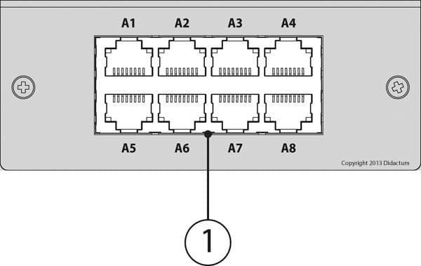
- 8 * RJ11 sensor ports for intelligent IP-sensors of manufacturer Didactum
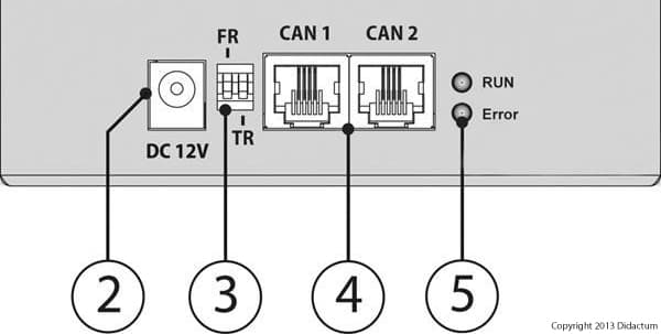
- External power supply (included)
- DIP switches with FR (Factory Restore) and TR (Terminator) switch
=> Please always leave the FR switch in the above position ("off").
=> The TR switch is used to terminate the CAN sensor expansion unit. In principle, the last CAN unit of the serial CAN bus chain should be always be terminated. Termination is used to avoid possible interfering signals on the whole CAN bus. On the factory side, the TR switch is in the above position ("off"). Remove power before changing the position of the DIP switch. - 2 * RJ12 CAN bus connections
- LED lights: The "RUN" light indicates the connection status of the CAN unit with IP-based main monitoring unit.
LED status of the sensor expansion unit
The "Error" LED light always indicates a faulty connection. The following signals can be output from this CAN Unit:
=> If the "Error" LED is permanently lit and the "RUN" LED flashes, this CAN Unit has no connection to the main monitoring device.
=> If the "Error" LED is permanently lit and the "RUN" LED is not lit, the CAN Unit is connected to the main monitoring unit but has not yet been configured.
=> If the "Error" LED is permanently off and the "RUN" LED is continuously on, the CAN unit connected to the main monitoring unit works perfectly.
Installation of the sensor expansion unit
Simply connect to included RJ12 patch cable to the "CAN 1“ port of the sensor expansion unit. Connect the other end of the patch cable to the CAN port of the previous CAN device or to the CAN port of your Didactum main monitoring unit.
If you need longer cable, the cable assignment of the RJ12 patch cable for CAN units and CAN sensors can be found here.
The total length of the CAN bus in the monitoring system 100 III / 500 II must not exceed 205 meters! The total CAN bus may consist of a maximum of 8 CAN sensors and / or CAN units.
Note:
Please adjust the terminator (TR) DIP switch. If the CAN unit is at the end of the CAN bus cabling, the terminator must be set to "ON". The DIP switch of the CAN sensor extension unit is switched to the lower position by help of a ballpoint pen tip. If CAN units or CAN sensors are located between the main unit and the last CAN device, these should not be terminated.
Using the external power supply
If only the CAN sensor expansion unit is connected to the CAN bus, the included external power supply does not have to be used. If the length of the RJ12 patch cable exceeds 10 meters and there are several CAN sensors and / or CAN units on the CAN bus cable, the power supply should be used.


On the right graphic, the TR switch is at the top position. This unit is not terminated. Always keep the FR (Factory Restore) switch in the upper position.

Configuration of the CAN unit in the web interface of the remote monitoring unit
Log on to the monitoring system via a web browser (Chrome / Firefox). Go to the "CAN configuration" menu item. Then click on the "Config" selection field and confirm the configuration of the CAN bus. The search for CAN units and digital CAN sensor is then started immediately.
Please note:
Depending on the total number of connected CAN sensors and / or CAN units, the scan of the CAN bus can take several seconds. After completion of the scan, the detected CAN units and CAN sensors are listed in tabular form. The intelligent sensors connected to the sensor expansion unit will be displayed in multilingual web interface under "System Tree“. Each IP-sensor be individually configured. Create in menu „Logic Schemes“ individual notifications and alerts in the form of actuator functions, SNMP traps, e-mail or SMS (via GSM modem or 3rd party Email to SMS gateway).
Hints:
If no CAN devices or CAN senors have been detected by the IP-based monitoring unit, please check the cables and the terminator setting (TR) of the CAN devices. As already mentioned, the last CAN unit / CAN sensor in CAN Bus has to be terminated via Terminater (TR) DIP switch. The CAN sensors and / or CAN units located between the main monitoring device and the last CAN device must not be terminated. Please check the status of the terminator (TR) jumpers or the DIP switches of each CAN device.

