Instructions for installation of the Monitoring System 300
The web-enabled Didactum Monitoring System 300 is a DIN rail device for remote monitoring technical rooms and industrial environments. As standard, this SNMP-enabled remote measuring and monitoring unit is delivered as follows (status 03/2020):
- 1x main unit Monitoring System 300
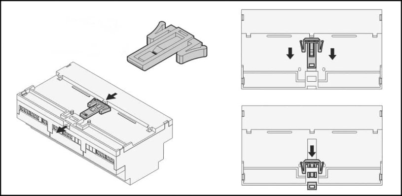
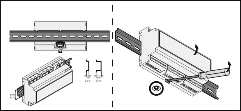
- 1x retaining clip for mounting on DIN rail
- 3x plastic covers for Monitoring System 300
- 1x RJ45 network cable
- 1x USB adapter cable
- Quick Guide Monitoring System 300
- Guarantee registration
The following options are available for the monitoring system. Note that these must be added when ordering:
- Warranty extension up to 72 months
- PoE power supply (Power over Ethernet)
- Internal LTE modem incl. 1x LTE antenna
- LTE additional antenna and GPS antenna (GPS coordinates)
- Power supply with 2 redundant voltage inputs
Notes: Make sure that the contents of the delivery correspond to the configuration specified above. Report a missing or damaged component to your local Didactum dealer or distributor. If transport damage has occurred, please contact the responsible delivery service.
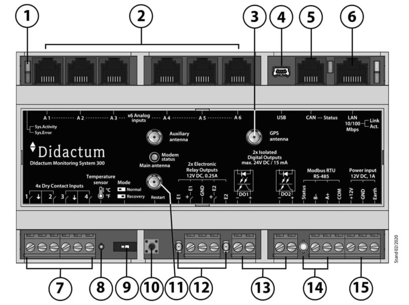
Description of the connections
- LED - LED status display Didactum Monitoring System 300
- Sensor ports – 6* RJ11 / RJ12 auto sensing connections for analog IP sensors
- GPS Antenna - optional SMA antenna connection for GPS antenna (extra charge)
- USB - 1* Mini USB 2.0 HS port for optional USB video surveillance camera or USB memory stick (data logger)
- CAN - 1* CAN bus connection for digital CAN multi sensors
- Ethernet port / PoE - 10/100 Mbit / s network port with optional PoE power supply
- Dry Contact Inputs - 4* inputs for floating contacts / digital dry contacts
- Temperature Sensor - 1* integrated temp sensor for self-monitoring of the remote monitor
- Recovery - 1* recovery switch for restoring the remote surveillance system
- Restart - reset button for restart
- Main LTE Antenna - Optional SMA antenna port for LTE modem, optional SMA connector for 2nd LTE antenna (extra charge)
- Relay outputs - 2* 12V 0.25A relay outputs (e.g. for sirens, flash lamps or forwarding alerts to building monitoring systems)
- Digital Outputs - 2* opto isolated digital / dry contact outputs
- RS-485 Modbus RTU - connection for Modbus RTU capable sensors and energy meters
- Power input - 12VDC 1A voltage input for external power supply (not included)
Power supply of Monitoring System 300
Notes: Please observe the applicable regulations and safety rules for electrical work. Hire an electrical specialist.
Please also observe the regulations for accident prevention and the occupational safety, operating and safety regulations. The technical specifications of the Monitoring System 300 must not be exceeded!
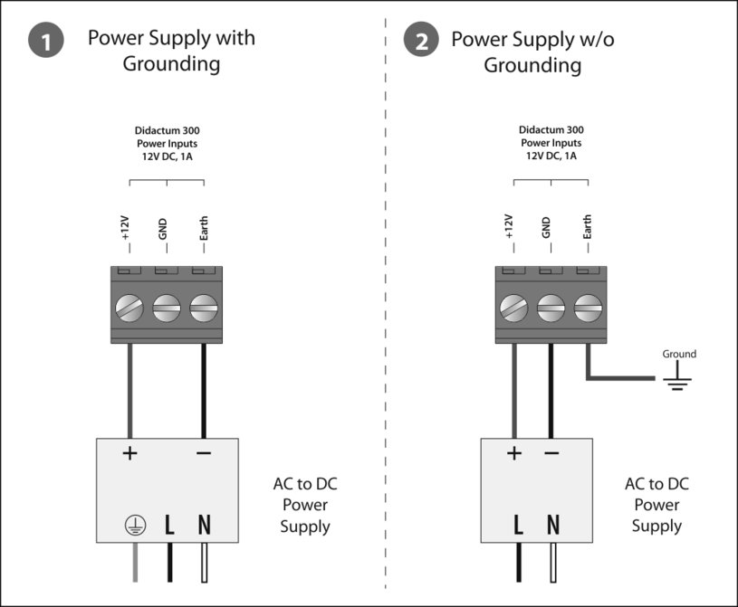
If you have ordered the Monitoring System 300 as a PoE model, the power is supplied via Power Over Ethernet (PoE). To do this, connect the remote monitoring unit to a PoE-capable network switch. Follow the instructions of the manufacturer of the PoE switch. The standard model of the Monitoring System 300 has no PoE power supply and requires a 12V DC, 1A power supply (not included in delivery). You can optionally order a suitable external power supply in the online store. Didactum also offers a special power supply unit with 2 redundant voltage inputs on request.
Connection of the I / O contacts to the web-enabled monitoring unit
Important note: When installing the floating contacts / dry contacts, pls check whether they are really current-free.
Otherwise the mainboard of the Ethernet-enabled remote monitor can be damaged. Further information on the subject of fault signal relays / dry contacts can be found in the data sheets of the manufacturers of your UPS system, emergency power generator or air conditioning system.
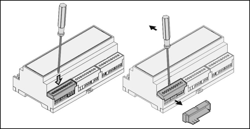
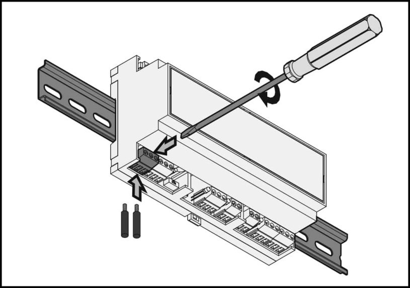
Tip from the technical editor: After installing the two-wire signal cables, use pliers to remove the respective plastic teeth from the associated cover. Then put the covers back on the I / O connections of the system. The respective two-wire I / O signal contact should always be labeled with a sticker. This simplifies later testing and maintenance work. An optional strain relief rail / cable clamp rail available in the Didactum online store prevents faulty cables from being accidentally pulled out during subsequent assembly work.


